Advanced narrow gap welding technology for thick walled
components
Conventional submerged arc welding (SAW) of V and U-groove welds (edge angles
up to 10 deg) has proven itself over the years and was the most frequently used
welding procedure for thick walled nuclear primary components. With constantly increasing wall thicknesses
the narrow-gap SAW (NGW) with parallel weld edges gradually replaced the open angle weld shapes and became the standard
welding technology for circumferential joints.
Hardly any design modifications have been necessary when introducing
narrow-gap SAW to replace conventional SAW, because only the edge angle
needed to be reduced, without having to change the weld-root buildup.
This approach is particularly useful in case when quality
requirements allow modifications of edge angles without needing expensive and time consuming additional WPQT.
Experience with conventional SAW processes (edge angles up to 10 deg)
indicates that very precise bead build-up on the seam edges is essential
for attaining in the base metal of an uniform HAZ with reduced
coarse-grain fractions.
This is made easier when welding at a vertical edge without
wire (electrode) deflection.
This basic condition of the narrow-gap SAW, combined with a suitable weld pool geometry and heat input can
completely and systematically eliminate all coarse-grain fractions by
the reheating effects of
subsequent weld seams.
A disadvantage of NGW is the more difficult repair of weld defects
during welding (e.g. side wall lack of fusion), especially when
they occur
in deeper regions of the gap. For such cases, a special repair concept
had to
be developed and qualified, consisting of a preparing step followed by the re-welding of
the affected place.
For the NGW of the mentioned MnMoNi reactor steel standard welding
conditions have been developed.
|
Two weld beads per layer are used for thicknesses
up
to 450 mm,
and three weld beads per layer for thicknesses
exeeding 450 mm (Figs 1 and 2).
Three weld beads per layer have been necessary for example for welding a
670 mm thick joint made between the dome section and the flange at
the closure head of the hitherto largest reactor pressure vessel -
"Atucha 2".
The macrograph made from the WPQT of this application can be seen in
Fig. 2a. In Fig. 2b is reproduced the closure-head design and the weld-joint
configuration.
The weld root - detail "A" -
has been
placed in a pocket provided additionally by shape
welding and machined down along the broken curve after heat treatment.
All parts of the "Atucha 2" RPV were forged in Japan.
|
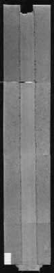
Fig. 1
|
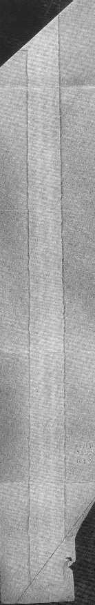
Fig.
2a
|
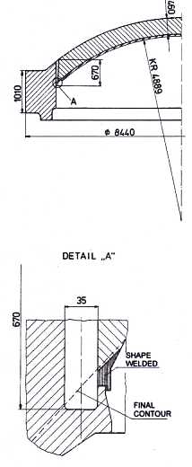
Fig.
2b
|
| Fig. 3 shows an overall view of the welding installation during
the welding of this application. The location of the milling unit developed for accompanying repairs is indicated
by a green arrow.
On the same platform were installed:
- The narrow-gap
welding unit,
- the automatic height control,
- the auxiliary
equipment for flux supply,
- vacuum flux recovery,
- slag break-down,
- slag
removal by suction, and
- the online television monitoring.
Some of
this auxiliary equipment was developed and supplied by the client
especially for
performing this circumferential weld.
|
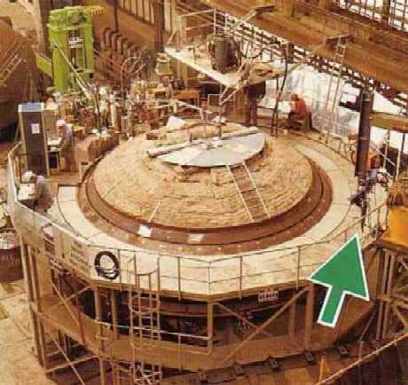
Fig. 3
|
|
The essential narrow gap welding equipment shown in Fig. 4 was
developed by GHH, and was installed on a welding boom. The wire
straightener comprising several modules is seen on the top. This modules are
infinitely variable, thus enabling a precise alignment of the wire.
Immediately below there is a weaving unit designed such that the welding
torch positions left-right (for two-bead welds) or left – right –
center (for three-bead welds) are obtained through a slight rotation (with
a catch) crosswise to the direction of welding.
The welding head rolling along the weld edges is kept in position by
means of adjustable spring tension. The welding head, itself, comprises an energized and a de-energized
part. The
welding wire is guided at the de-energized part without changing the distance to
the weld edge. The energized part is also kept pressed to the welding wire by
spring tension. This compensates the wear of the contact
jaw and brings about a
satisfactory current transfer. |
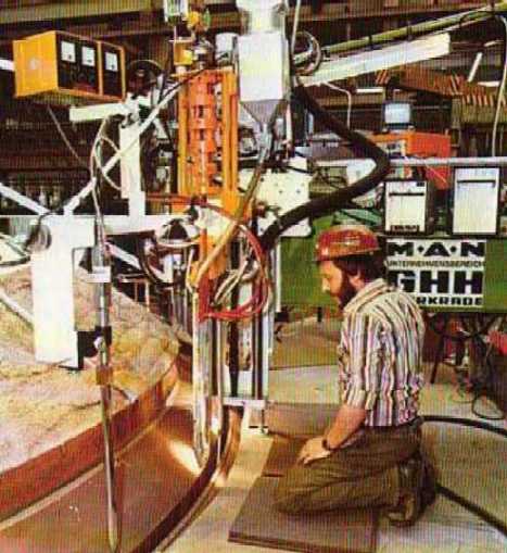
Fig. 4
|